Note that you can either load Tutorial_2_Manual_NU-100.sxt from the Examples folder, if you want to skip the first tutorial in this series, or you directly continue from the first tutorial here.
Organizing Structures in a File
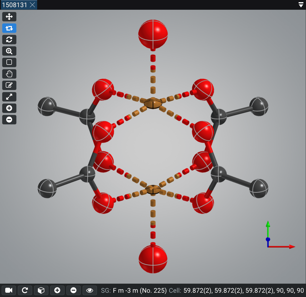
In your Structure View you should see the copper(II) paddlewheel core of NU-100 (Figure 1). We now want to visualize the full unit cell of NU-100, which is a metal-organic framework and a 3D periodic coordination polymer.
To keep the original paddlewheel core in the view, we will first duplicate the current structure by clicking on “Structures > Duplicate Structure” in the menu.
This creates another structure in the Tutorial_2_Manual_NU-100.sxt file, which is a copy of the current structure.
shapeXT files can contain multiple structures, which can be used to visualize different parts of a structure or different structures in one file.
You can also import other structures into the current file via “File > Import > Import Structure”.
Structures can be removed via “Structures > Remove Structure” in the menu.
Right now, the two structures are identical, but we will now change the second structure to visualize the full unit cell of NU-100. First of all, let us rename the duplicated structure. Click “General > Structure” in the Navigator, you should now see the “Structure Properties” in the Inspector in which you can change the name by clicking into the input field. Change the structure name to something like “NU-100 Unit Cell”.
Handling Multiple Structures
In addition, when you work with many structures, it is helpful to change the tab color of the structure view. Activate the checkbox at the “Tab Color” property in the Inspector and select a color of your choice. Note that the color in the tab of the structure view has changed to the selected color.
Did you notice there is a Previews window next to the Navigator? Click on the Previews tab to see a small preview of the currently opened structures. There should be two identical previews, except for the structure name and the tab color which is indicated by a small colored triangle in the top right. You can switch between the two structures by clicking on the preview of the desired structure. By right clicking, a context menu opens where you can change the preview size. Leave the Previews window by clicking on the Navigator tab.
Filling the Unit Cell
In the next step, we want to fill the unit cell of NU-100. You can achieve this by clicking on “Build > Fill Unit Cell” in the menu. As an alternative, you can also click on the “Fill” button in the bottom toolbar of the structure view, which opens a popup menu with even more options. These options give quick access to the most common filling options, e.g. “Fill Asymmetric Unit”, “Fill Unit Cell”, and “Fill Cell Range”. There are also various presets for filling supercells. If you want a specific filling option, you can click on “Fill Cell Range” which opens a dialog window that lets you define the cell boundaries and gives you an estimate of the number of atoms that will be generated.
Once you have filled the unit cell, you will notice that the number of atoms has increased in the Navigator window from 20 to 3368 in an instant.
After the unit cell fill, the view has not automatically changed.
You can reset the view by double tapping the X key or by clicking on “View > Reset View” in the bottom toolbar.
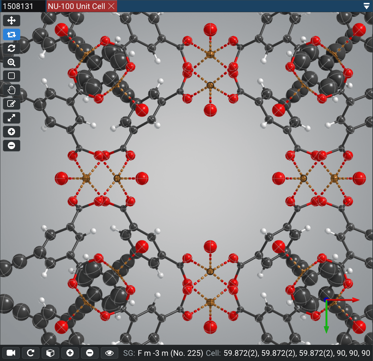
After resetting the view, zoom in a bit so you can see a view similar to Figure 2.
Atom Styles
From this view, you will notice that some atoms of the linker molecules are shown as large ellipsoids. This indicates that these atoms have a high atomic displacement parameter (ADP). You can see the individual ADP values when you hover over the atoms with the mouse cursor. By default, shapeXT displays atomic displacement parameters as ellipsoids, when ADP values are given in the structure file. The default setting is to show the thermal ellipsoids for a 50% probability level.
You can adjust the probability level for the whole structure by changing the value in the Inspector by clicking “General > Styles” in the Navigator first.
The probability level property will appear in the Inspector at the “Ellipsoids” category.
Use the slider to change the probability level to a lower value, e.g. 30%.
You can also press Ctrl and click on the slider to enter a specific value in the input field.
You will notice that the changes are immediately applied to the structure view, and the ellipsoids have become smaller.
There is also an option to show the atoms as spheres instead of ellipsoids. You can individually change the atom style of a single atom by clicking on the atom and changing the “Style” property in the Inspector. However, this would be very tedious for a large number of atoms. Instead, you can change the atom style for all atoms via the main menu “Display > Set Atom Style > Spheres”. Note that there are even more options to change the atom style.
Polyhedra
For the central copper atoms of the paddlewheel core, you can add coordination polyhedra to visualize the coordination environment. Right-click on one of the copper atoms and hover over “Create Polyhedron” in the context menu. You can create a polyhedron from the coordination sphere of that specific atom, or you can create a polyhedron from selected atoms. If you have a large number of atoms, it is more convenient to create polyhedra for all atoms of the same chemical element or all symmetry-equivalent atoms in the structure. Hence, choose “Create Polyhedron > To Same Element (Cu)” which will create polyhedra for all copper atoms in the structure.
Double tap the X key to reset the view again.
You will notice that there have been 50 polyhedra created, but there are copper atoms in the unit cell that do not have a polyhedron.
This is because polyhedra are only created for atoms with a completed coordination sphere.
Zoom in a bit to a copper(II) ion with an incomplete coordination sphere.
Right click on the copper atom and select “Expand All of the Same Element (Cu)” in the context menu.
This completes all coordination spheres of all copper atoms in the unit cell.
Right click on the same copper atom again, and choose “Create Polyhedron > To Same Element (Cu)” again.
Press the X key once to reset the zoom level.
Now, you can see that all copper atoms have a coordination polyhedron.
Finishing the View
To get a better view of the structure, you can change the camera projection from perspective to orthographic.
You can always toggle between these two camera projections by pressing the F3 key or via the “View” button in the bottom toolbar of the structure view.
Note that the zoom level is not changed when switching between the two camera projections.
To adjust the zoom level, press the X key once, use the Shift+W and Shift+S keys to manually zoom in and out, or use the mouse action Zoom Camera.
Let’s change the color of the polyhedra by clicking on a single polyhedron. In the Inspector at “Style”, change the color property, e.g. to a color without transparency by dragging the alpha slider to the top. To apply the color change to all polyhedra, click on the “Apply” button in the Inspector and choose “to Polyhedra of the Same Type” in the context menu. Note that you can also copy the style and paste it to other polyhedra in other structures.
Sometimes, it is also helpful to hide hydrogen atoms to get a better view of the structure.
shapeXT can toggle the visibility of hydrogen atoms by pressing the F2 key or by clicking on “Display > Show Hydrogen Atoms” in the menu.
This way, you can quickly change the visibility of hydrogen atoms even at the last stage of preparing an image for a publication or presentation.
Speaking of last changes, you can scale the size of the object types such as atoms and bonds in the Inspector at “General > Styles” by changing the “Scale” properties. E.g. for NU-100, you can reduce the atom scale to 0.80 and increase the bond scale to 1.20 to get a better view of the structure.
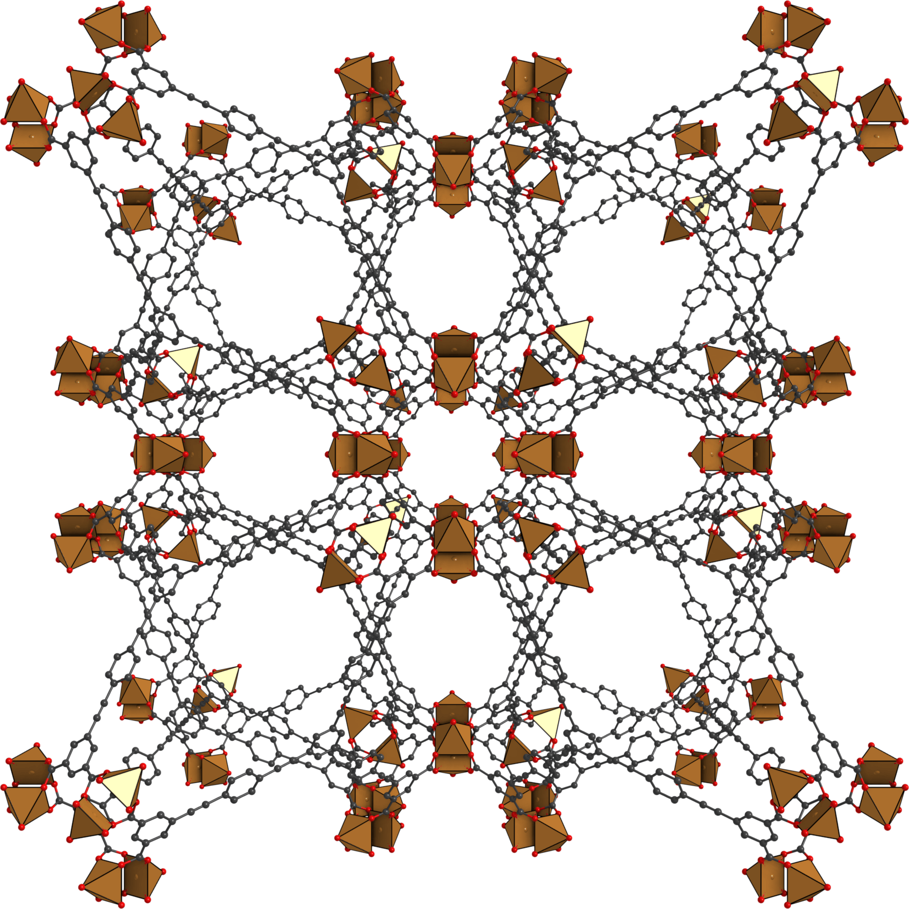
Now, you can render a final high-resolution image of the NU-100 unit cell by clicking on “Render Image To File” in the camera menu (sidebar). Congratulations, you did it! Your output image should look similar to Figure 3. If you want to further enjoy your work, you can rotate the structure by clicking on the “Rotation” button in the bottom toolbar of the structure view. Change the green slider for the y-axis rotation to some small value, e.g. 2 deg/s to start the rotation, and enjoy!